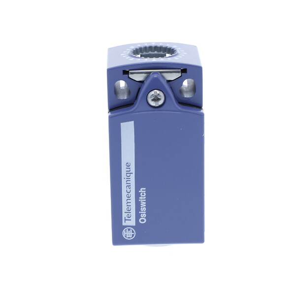
XCKP2118P16
Limit switch, Limit switches XC Standard, XCKP, thermoplastic roller lever, 1NC+1 NO, snap, M16

COMMERCIALISED
Expand all
Datasheet
Range of product
Telemecanique Limit switches XC Standard
Series name
Standard format
Product or component type
Limit switch
Device short name
XCKP
Sensor design
Compact form A conforming to CENELEC EN 50047
Body type
Fixed
Head type
Rotary head
Material
Plastic
Body material
Plastic
Head material
Zamak
Fixing mode
By the body
Movement of operating head
Rotary
Type of operator
Spring return roller lever thermoplastic
Type of approach
Lateral approach, 2 directions
Contacts type and composition
1 NC + 1 NO
Contact operation
Snap action
Tracks
24/40 mm
Switch actuation
By 30° cam
Electrical connection
Screw-clamp terminals, clamping capacity: 1 x 0.34...2 x 1.5 mm²
Cable entry
1 entry tapped for M16 x 1.5 cable gland, cable outer diameter: 4-8 mm
Contacts insulation form
Zb
Positive opening
With
Repeat accuracy
0.1 mm on the tripping points with 1 million operating cycles
Contact code designation
A300, AC-15 (Ue = 240 V), Ie = 3 A, Ithe = 10 A conforming to IEC 60947-5-1 appendix A, Q300, DC-13 (Ue = 250 V), Ie = 0.27 A conforming to IEC 60947-5-1 appendix A
Resistance across terminals
25 MOhm conforming to IEC 60255-7 category 3
Terminals description ISO n°1
(13-14)NO
(21-22)NC
(21-22)NC
Shock resistance
50 gn for 11 ms conforming to IEC 60068-2-27
Vibration resistance
25 gn (f= 10-500 Hz) conforming to IEC 60068-2-6
IP degree of protection
IP66 conforming to IEC 60529, IP67 conforming to IEC 60529
IK degree of protection
IK04 conforming to IEC 62262
Electrical shock protection class
Class II conforming to IEC 61140, class II conforming to NF C 20-030
Protective treatment
TC
Product certifications
CCC
CSA
UL
CSA
UL
Standards
CSA C22.2 No 14
IEC 60204-1
IEC 60947-5-1
UL 508
IEC 60204-1
IEC 60947-5-1
UL 508
Unit type of package 1
PCE
Number of units in package 1
1
Package 1 height
3.2 CENTIMETER
Package 1 weight
0.116 KILOGRAM
Package 1 width
4.6 CENTIMETER
Package 1 length
12.6 CENTIMETER
Unit type of package 2
S02
Number of units in package 2
60
Package 2 height
15 CENTIMETER
Package 2 width
30 CENTIMETER
Package 2 length
40 CENTIMETER
Package 2 weight
7.595 KILOGRAM
Unit type of package 3
CAR
Number of units in package 3
1
Package 3 height
3.4 CENTIMETER
Package 3 width
5 CENTIMETER
Package 3 length
13 CENTIMETER
Package 3 weight
0.119 KILOGRAM
Indivisible sale quantity
1
California proposition 65
WARNING: This product can expose you to chemicals including: Diisononyl phthalate (DINP), which is known to the State of California to cause cancer, and Di-isodecyl phthalate (DIDP), which is known to the State of California to cause birth defects or other reproductive harm. For more information go to www.P65Warnings.ca.gov
Expand all
Technical Drawings
Dimensions

- (1) Tapped entry for M16 x 1.5
- (2) 2 elongated holes Ø 4.3 x 6.3 mm on 22 mm centres, 2 holes Ø 4.3 on 20 mm centres.
- (3) 2 x Ø 3 holes for support studs, depth 4 mm.
Mounting with Cable Entry
Position of Cable Gland
- (1) Recommended
- (2) To be avoided
Mounting with Rotary Heads and Levers
Type of Cam
- (1) Recommended
- (2) To be avoided
Setting-up with Head ZCE01 and ZCE09
- (1) Tightening torque (Min : 1) (Max : 1.5)
- (2) Tightening torque (Min : 0.8) (Max : 1.2)
Wiring Diagram
2-pole NC + NO Snap Action

Characteristics of Actuation
Switch Actuation by 30° Cam
Functionnal Diagram
- (1) Closed
- (2) Open
- (4) Tripping
- (5) Resetting
Expand all
Documents & Downloads
Document name
Date
Size
2024-07-15
68162797
Document name
Date
Size
2025-01-13
8843040
2024-04-01
6172346
Document name
Date
Size
2024-07-18
1596
2024-07-18
1596
2024-07-18
1596
2024-07-18
1596
2024-07-18
1596
2024-07-18
1596
2024-07-18
1596
2024-07-18
1596
2024-07-18
1596
2024-07-18
1596
2024-07-18
1596
2024-07-18
1596
2024-07-18
1596
2024-07-18
1596
2024-07-18
1596
2024-07-18
1596
2005-01-13
13846
2005-01-13
19411
2005-01-13
3280
2005-01-13
4253
2005-01-13
45154
2005-01-13
48146
2005-01-13
52293
2005-01-13
53962
2005-01-13
6730
Document name
Date
Size
2026-04-14
110208
2026-04-13
108894
Document name
Date
Size
Back to top