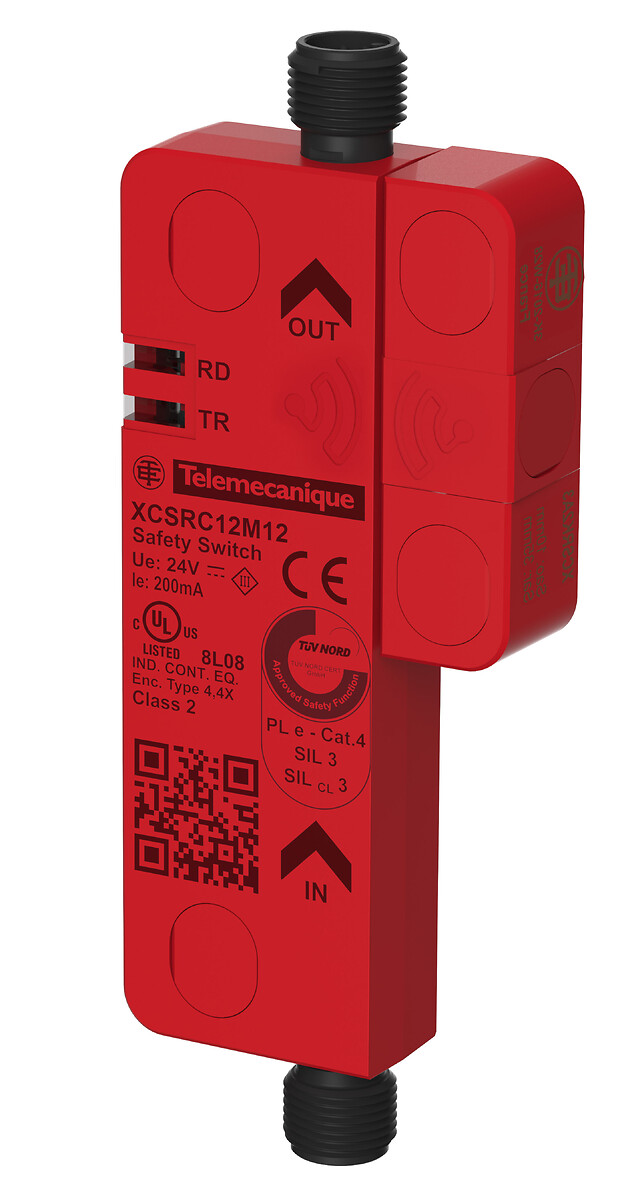
XCSRD210MDB
Telemecanique Safety switches XCS, diagnostic module for XCSRC Daisy Chain models, Modbus RTU

COMMERCIALISED
Expand all
Datasheet
Range of product
Telemecanique Safety switches XCS
Accessory / separate part category
Diagnostic accessories
Accessory / separate part type
Diagnostic module
Accessory / separate part destination
RFID safety switch
Product compatibility
XCSRC...2M12
Local signalling
Green, orange and red 2 LEDs
[Ue] rated operational voltage
24 V DC (- 20...10 %)SELV or PELV
Unit type of package 1
PCE
Number of units in package 1
1
Package 1 height
6.5 CENTIMETER
Package 1 width
4.3 CENTIMETER
Package 1 length
9.5 CENTIMETER
Package 1 weight
0.117 KILOGRAM
Unit type of package 2
S01
Number of units in package 2
12
Package 2 height
15 CENTIMETER
Package 2 width
15 CENTIMETER
Package 2 length
40 CENTIMETER
Package 2 weight
1.591 KILOGRAM
Indivisible sale quantity
1
California proposition 65
WARNING: This product can expose you to chemicals including: Diisononyl phthalate (DINP), which is known to the State of California to cause cancer, and Di-isodecyl phthalate (DIDP), which is known to the State of California to cause birth defects or other reproductive harm. For more information go to www.P65Warnings.ca.gov
Expand all
Documents & Downloads
Document name
Date
Size
2024-10-31
31713778
Document name
Date
Size
2017-03-01
2329593
2024-12-02
256729340
2024-12-02
4814059
Document name
Date
Size
7/18/2024
140022
7/18/2024
142539
7/18/2024
1799764
7/18/2024
25368
7/18/2024
30455
7/18/2024
30647
7/18/2024
31513
7/18/2024
36439
7/18/2024
39971
7/18/2024
49055
7/18/2024
50777
7/18/2024
63799
7/18/2024
65283
7/18/2024
66632
7/18/2024
82361
Document name
Date
Size
2026-04-14
109516
2026-04-13
108829
Document name
Date
Size
2024-06-27
191465
Document name
Date
Size
2026-01-26
4343561
Document name
Date
Size
2024-01-30
553574
Back to top