XT530B1PCL2
Capacitive proximity sensors XT, cylindrical M30, brass, 4-wire, Sn 10 mm, cable 2 m, 1 NC + 1 NO

Commercialised
Expand all
Datasheet
Product or component type
Sensor
Sensor type
Capacitive proximity sensor
Product specific application
Detection of insulated or conductive materials
Sensor name
XT5
Sensor design
Cylindrical M30
Size
64 mm
Body type
Fixed
Detector flush mounting acceptance
Flush mountable
Material
Metal
Enclosure material
Nickel plated brass
Type of output signal
Discrete
Wiring technique
4-wire
Discrete output function
1 NC + 1 NO
Output circuit type
DC
Discrete output type
PNP
Electrical connection
Cable
[Us] rated supply voltage
24 V DC with reverse polarity protection
Delay response
15 MILLISECOND
IP degree of protection
IP67 conforming to IEC 60529, IP65 conforming to IEC 60529
ISO thread
M30 x 1.5
Detection face
Frontal
Front material
PBT
Differential travel
< 0.2 x Sr
Repeat accuracy
< 0.1 x Sr
Wire insulation material
PVC
Status LED
Output state indication: 1 LED (yellow), power status: 1 LED (green)
Residual current
0.1 mA open state
Protection type
Short-circuit protection
Switching frequency
<= 25 Hz
Voltage drop
<2.5 V (closed)
Current consumption
< 15 mA
Delay first up
300 MILLISECOND
Delay recovery
15 MILLISECOND
Marking
CE
Setting-up
Sensitivity by potentiometer
Standards
IEC 60947-5-2
UL 61010-1
UL 61010-1
Product certifications
cULus
Vibration resistance
10 gn amplitude = 1 mm (f = 10-55 Hz) conforming to IEC 60068-2-6
Shock resistance
30 gn for 11 ms conforming to IEC 60068-2-27
Electrical insulation class
Class III conforming to IEC 61140
Unit type of package 1
PCE
Number of units in package 1
1
Package 1 height
4.5 CENTIMETER
Package 1 width
13 CENTIMETER
Package 1 length
13.5 CENTIMETER
Package 1 weight
0.206 KILOGRAM
Unit type of package 2
S02
Number of units in package 2
30
Package 2 height
15 CENTIMETER
Package 2 width
30 CENTIMETER
Package 2 length
40 CENTIMETER
Package 2 weight
6.502 KILOGRAM
Indivisible sale quantity
1
California proposition 65
WARNING: This product can expose you to chemicals including: Diisononyl phthalate (DINP), which is known to the State of California to cause cancer, and Di-isodecyl phthalate (DIDP), which is known to the State of California to cause birth defects or other reproductive harm. For more information go to www.P65Warnings.ca.gov
Expand all
Technical Drawings
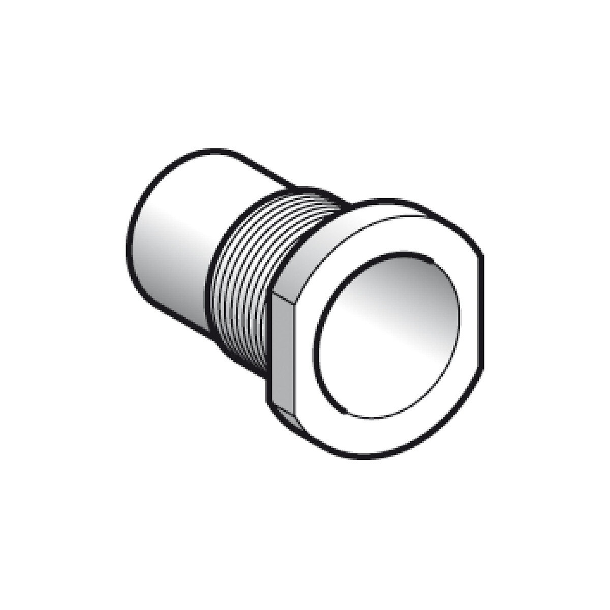
Dimensions
Dimensions

Mounting and Clearance
Mounting and Clearance
Sensitivity adjustment

Mounting and Clearance
Mounting and Clearance
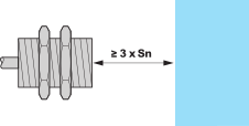
Minimum Mounting Distances
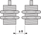
Minimum Mounting Distances
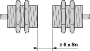
Minimum Mounting Distances
Connections and schema
Connections and schema
Wiring diagram

Expand all
Documents & Downloads
Document name
Date
Size
7/18/2024
396231
Document name
Date
Size
2024-06-27
3043803
Document name
Date
Size
2025-02-28
250607
2025-02-28
239766
Document name
Date
Size
2024-01-19
569861
Document name
Date
Size
Back to top