XUM2APCNM8
Photoelectric miniature receiver XUM, thru-beam, Sn 15 m, 12...24 VDC, M8, PNP, NO/NC
END OF COMMERCIALISATION End of commercialization date : April 27th 2022 End of service date : April 27th 2022
XUM2APCNM8 is replaced by the following product:

Quantity : 1
Expand all
Datasheet
Range of product
Telemecanique Photoelectric sensors XU
Sensor name
XUM
Series name
General purpose single mode
Product specific application
Not applicable
Enclosure material
PBT
Electronic sensor type
Photo-electric sensor
Sensor design
Miniature
Material
Plastic
Electrical connection
1 male connector M8, 4 pins
Wiring technique
3-wire
Detection system
Thru beam
Emission
Red thru beam
Kit composition
Transmitter + receiver XUM2AKCNM8T + XUM2APCNM8R
Discrete output function
1 NO or 1 NC programmable
[Us] rated supply voltage
12...24 V DC
Type of output signal
Discrete
Supply circuit type
DC
Switching frequency
500 Hz
Discrete output type
PNP
Delay response
1 MILLISECOND
Setting-up
Sensitivity adjustment
Current consumption
35 mA no-load
Output type
Solid state
Switching capacity in mA
<= 100 mA (overload and short-circuit protection)
Lens material
PMMA
Status LED
1 LED (yellow) for output state, 1 LED (red) for instability
Sensing range
> 5...15 m
Maximum voltage drop
<1.5 V (closed state)
Delay first up
30 MILLISECOND
Delay recovery
1 MILLISECOND
Shock resistance
30 gn (duration = 11 ms) conforming to IEC 60068-2-27
IP degree of protection
IP67 double insulation conforming to IEC 60529, IP65 double insulation conforming to IEC 60529
Vibration resistance
7 gn, amplitude = +/- 1.5 mm (f = 10-55 Hz) conforming to IEC 60068-2-6
California proposition 65
WARNING: This product can expose you to chemicals including: Diisononyl phthalate (DINP), which is known to the State of California to cause cancer, and Di-isodecyl phthalate (DIDP), which is known to the State of California to cause birth defects or other reproductive harm. For more information go to www.P65Warnings.ca.gov
Unit type of package 1
PCE
Number of units in package 1
1
Expand all
Technical Drawings
Receiver's Dimensions
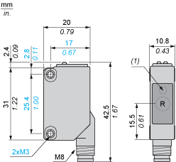
- R : Reception
- (1) Output state LED on front face
Transmitter's Dimensions
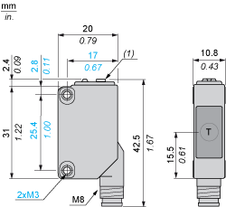
- T : Transmission
- (1) Potentiometer
Mounting and Clearance
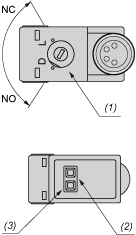
- (1) Configuration switch
- (2) Output state LED
- (3) Stability and power on LED
Mounting and Clearance
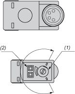
- (1) Adjustment potentiometer
- (2) Power on LED
Connections and Schemes
M8 Connector

- 1 : (+)
- 3 : (-)
- 4 : OUT/Output
Connections and Schemes
PNP
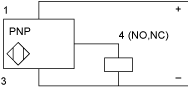
- 1 : (+)
- 3 : (-)
- 4 : OUT/Output
Connections and Schemes
Transmitter DC
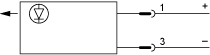
- 1 : (+)
- 3 : (-)
- 4 : OUT/Output
Detection Curves

- (Y) Parallel movement (cm)
- (X) Distance (m)
Expand all
Documents & Downloads
Document name
Date
Size
2024-02-07
35721052
2024-02-07
35820728
Document name
Date
Size
2024-07-18T00:00:00.000Z
221348
2024-07-18T00:00:00.000Z
23865
2024-07-18T00:00:00.000Z
25277
2024-07-18T00:00:00.000Z
25340
2024-07-18T00:00:00.000Z
26427
2024-07-18T00:00:00.000Z
27957
2024-07-18T00:00:00.000Z
28091
2024-07-18T00:00:00.000Z
36376
2024-07-18T00:00:00.000Z
41246
2024-07-18T00:00:00.000Z
42070
2024-07-18T00:00:00.000Z
47131
2024-07-18T00:00:00.000Z
49678
2024-07-18T00:00:00.000Z
51185
2024-07-18T00:00:00.000Z
79237
2024-07-18
88396
2024-07-18T00:00:00.000Z
944911
Back to top
